Landscapes - Material Concepts
A landscape material is one which is applied to an Unreal Engine landscape object. It is created similarly to any other material in Unreal but can use some special nodes (such as the Landscape Layer Blend node) which only work inside landscapes materials.
While this page is about landscape materials in Unreal Engine, it does not tell you how to make one, it describes how they are made, how important features work, and looks at alternative approaches used in commonly available examples.
Background
This is part of a series of articles about Landscapes, these articles include:
Landscapes - Building GDAL
Landscapes - Material Concepts
Landscapes - Nanite Tessellation
Landscapes - Using Real Location Data
Landscapes - World Partition and Tiling
Landscape Painting
Conceptually a landscape material draws textures on the landscape. Each type of texture, for example rocks, grass and snow, is usually added in a separate group, and these groups are usually referred to as "layers", as an the "grass layer" or the "rock layer".
In addition, Unreal uses the term "layers" to describe paintable layers which can be manually painted onto a landscape using the editor.
If the landscape material contains a Landscape Layer Blend node, then the material creates paintable layers which can be used to manually paint the landscape. This is not always the case; some landscape materials do not contain a Landscape Layer Blend node.
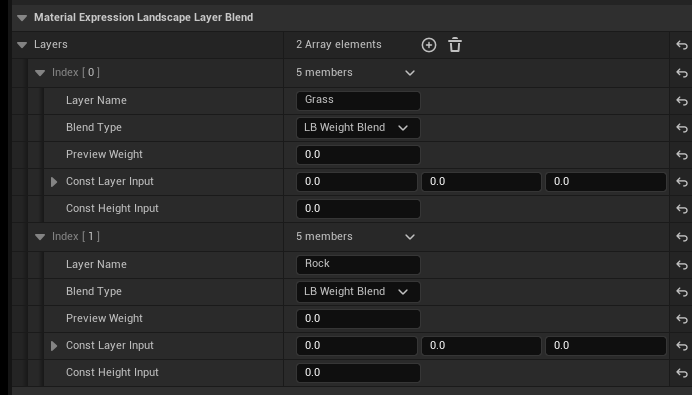
The names of the paintable layers are defined in the properties of the Landscape Layer Blend node, for example this node defines two paintable layers called "Grass" and "Rock":
When the landscape material has paintable layers defined in a Landscape Layer Blend node then the paintable layers appear on the Landscape Mode Paint tab:
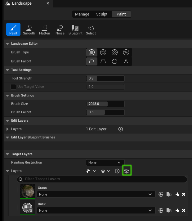
The highlighted button can be used to refresh these layers if they don't appear or as you change the material to add or delete paintable layers.
Auto Materials
A landscape auto material is one which applies different textures to the different parts of the landscape without requiring manual painting. It usually defines various layers such as rock, soil, grass, snow etc. and usually contains:
- rules which define which layer(s) to apply depending on the height or slope of the terrain
- rules for blending layers together when they overlap
- rules controlling transitioning from one layer to another
- parameters which control all of the above
- parameters which control texture tiling
A single landscape material can be both an auto material and create paintable layers for manual painting.
Depending on how they are written, there is a performance impact associated with using auto textures. Sampling the slope of the landscape has an overhead, which could be reduced by having a texture which contains this data and sampling that instead.
Manually Painting a Landscape
As described above, if the landscape material contains a Landscape Layer Blend node, then the material creates paintable layers which can be used to manually paint the landscape. Before it can be used for painting each paintable layer needs a LayerInfo object, like the one for the grass layer shown here:
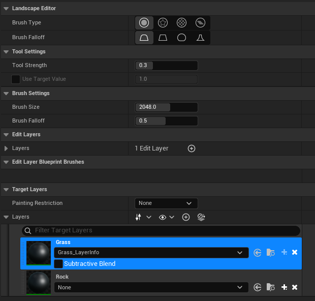
These LayerInfo objects store the details of where the layer is painted on the landscape.
Material Construction
This section highlights some approaches used in constructing a landscape master material.
Material Attributes
When the material is first created there will be a New Material node created for the output of the material. Select the node and check the "Use Material Attributes" checkbox to change the node to a material attributes node:
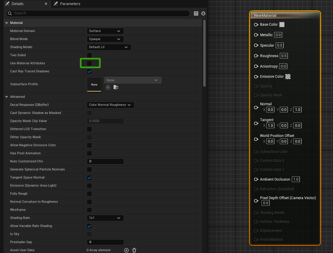
This means that what is passed from node to node in the material graph is a set of material attributes, and we can use special nodes which operate on all the attributes at the same time, for example blending all the attributes from two attribute sets.
Materials or Functions
If we have two layers and use nodes directly, we get a graph like the one shown below, where each material has a texture, a normal texture, and other textures such as ambient occlusion, roughness, displacement etc. depending on what channels are provided in the texture set. Each layer is connected to its own Make Material Attributes node, and then these layers are blended:
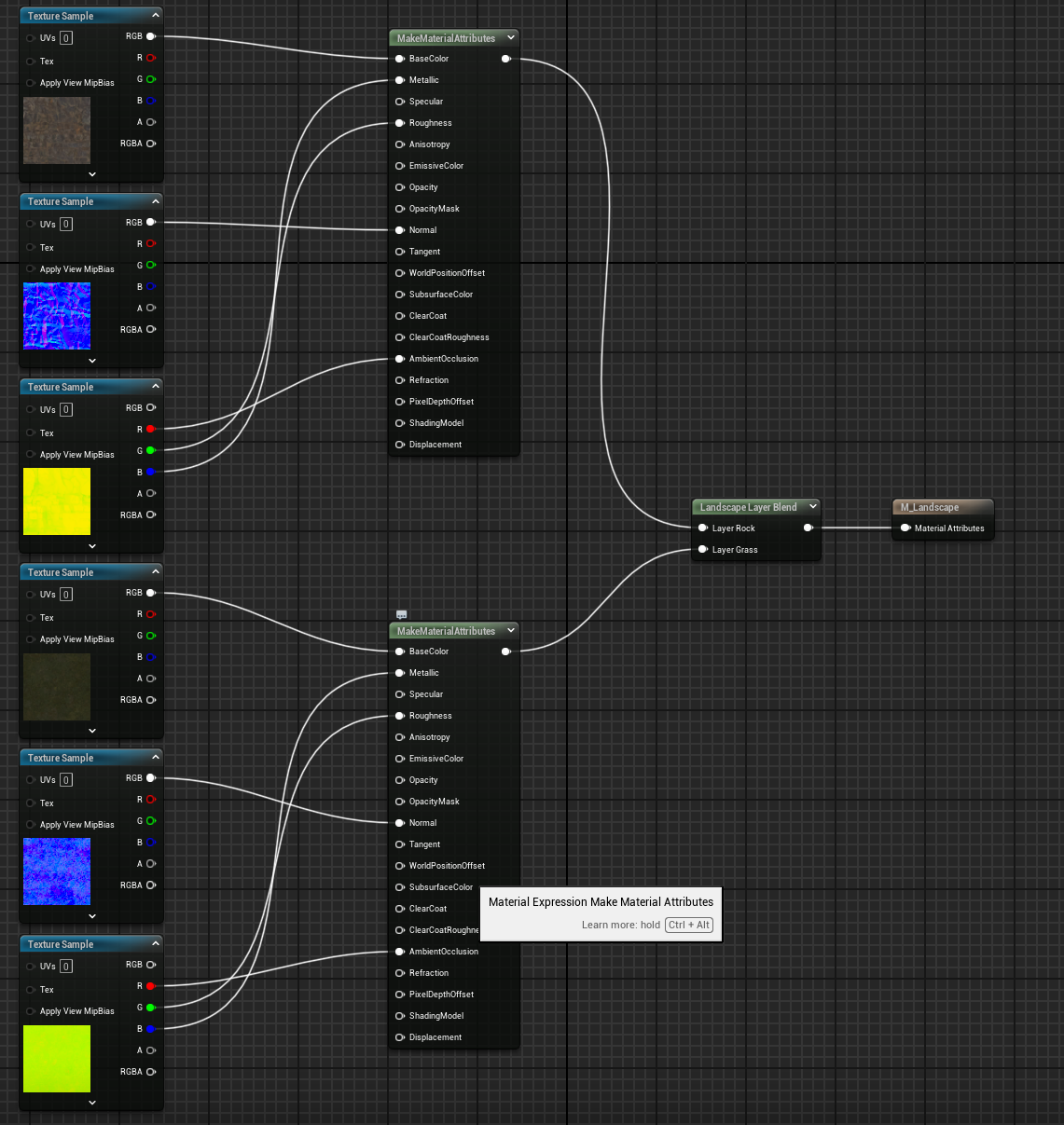 This is manageable enough but we might need to add:
- constant scalar nodes for metallic, specular and roughness
- different tiling multipliers to make each texture tile differently close up and far away
- color tints
- normal intensity scaling
Each of these things will need to be added for every layer, so instead of duplicating the nodes we can move most of the complexity into a function which looks something like this:
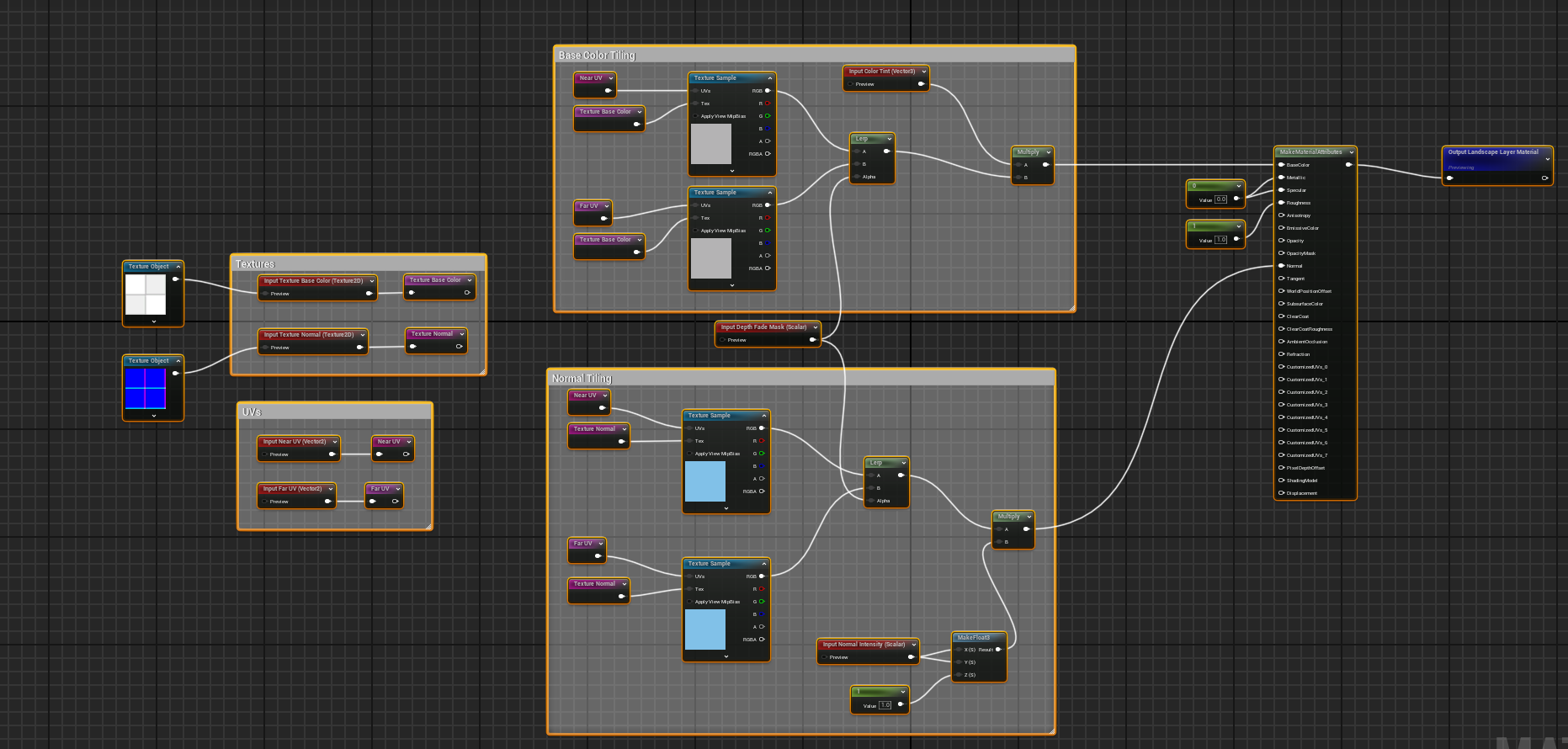
and then call the function for each layer like this:
Using a function like this makes the material easier to maintain and makes it quicker to add more layers. (Not all function inputs are connected, but it's enough to illustrate the point).
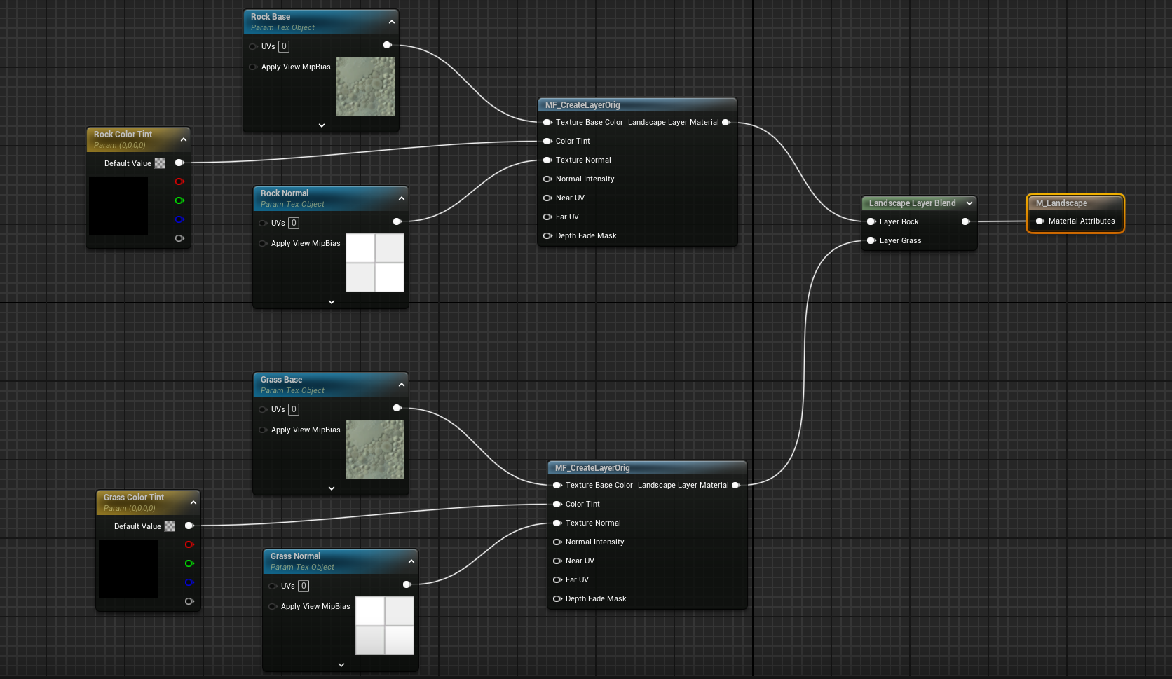
Another approach (used in the Epic Project Titan sample) is to have each layer define its own function which contains all the textures:
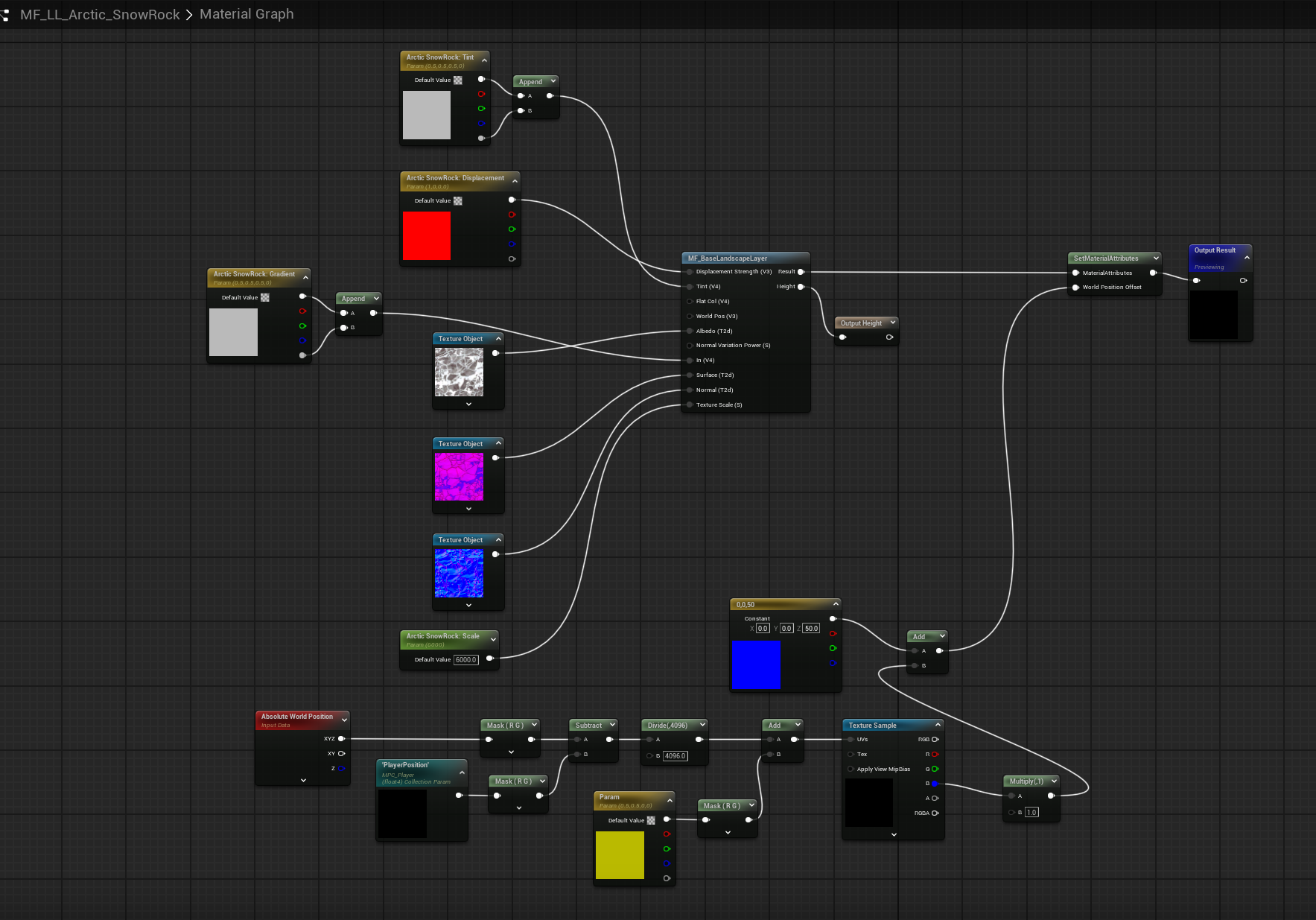
This still centralizes common code (in the MF_BaseLandscapeLayer material function) but means that each layer is a separate object which helps with sharing and source control when you have a large number of people working on the project.
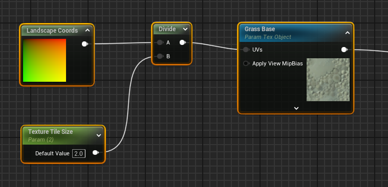
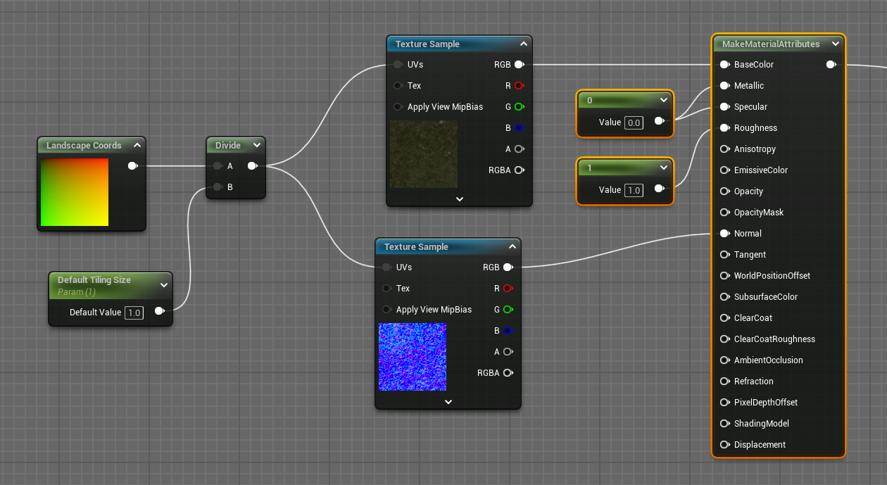
Texture Sizes
Most landscape materials provide a parameter for each layer which is used to change the tiling of each texture. This might be done with one parameter for all textures:
Or with different values for near and far textures, known as Distance Tiling:
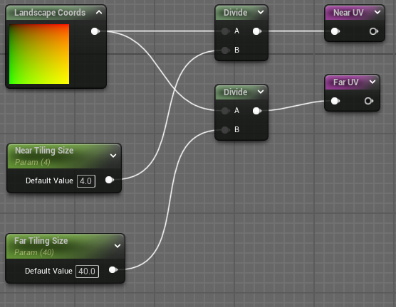
If there are two tiling sizes, then the material function which creates the layer needs to sample the texture twice at different UVs and blend the results:
As shown above there also needs to be a parameter controlling the distance at which the blending occurs, i.e. where does near change to far. Having two tiling sizes make the landscape look better but sampling the textures twice has a performance overhead.
Ideally a material will have:
- different tile sizes for each layer
- properties which recognise that textures are not all the same size. This sand texture is a scan of a 4 x 4 m area, whereas this windswept sand texture is a 4 x 2 m area. If they are to be presented in-game at their real-life dimensions the scaling will be different for each texture and needs to consider that not all textures are square.
Blending
Layers are typically organised in a layered approach, with, say, a base dirt layer, then grass on top of the dirt, then rocks on top of the grass and dirt, then snow on top of the rocks and grass and dirt.
These layers are blended using a Blend Material Attributes node as shown here:
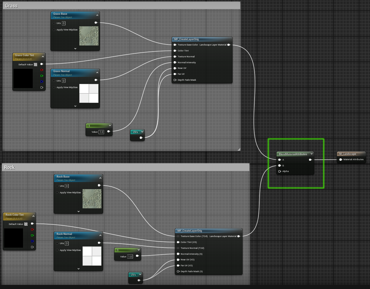
The Blend Material Attributes node takes two sets of material attributes (A and B) and an alpha value, which is a single float. The node blends the two sets of material attributes depending on the alpha value. It outputs the A input when alpha is 0, the B input when alpha is 1, and a mixture of A and B for values between 0 and 1. This is calculated on a per-pixel basis.
Height Blending
For some layers such as snow it makes sense to consider the landscape height, so that for example snow only appears above 1000m. This is approached by creating a parameter which specifies what the height is where we start blending between snow and the lower layers, and using an Absolute World Position node to get the Z position (which is the height) of the landscape. This can be done like this:
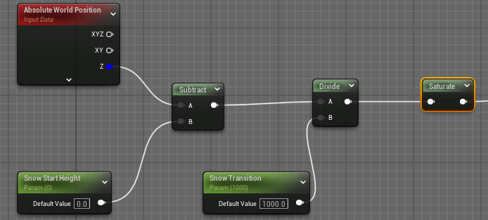
Note the Snow Transition parameter which defines the vertical distance over which the snow will start. If this is zero then we would get a sharp horizontal line whereas non-zero values blur this line.
This shows the sharp line when Snow Transition is 0:
and a gentler blending when the Snow Transition is 40:
Also note the use of the Saturate node. This is equivalent to clamping between 0 and 1 but on some GPUs is less expensive or even free. This is used because the Blend Material Attributes node expects inputs between 0 and 1, values outside this range can have odd results such as turning the landscape black.
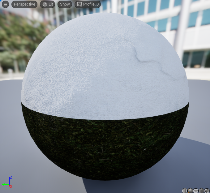
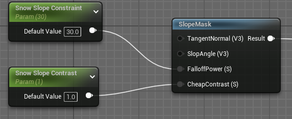
Slope Blending
Here the idea is that grass does not grow on vertical cliff faces, so we want the slope of the terrain to influence which layer appears on the terrain.
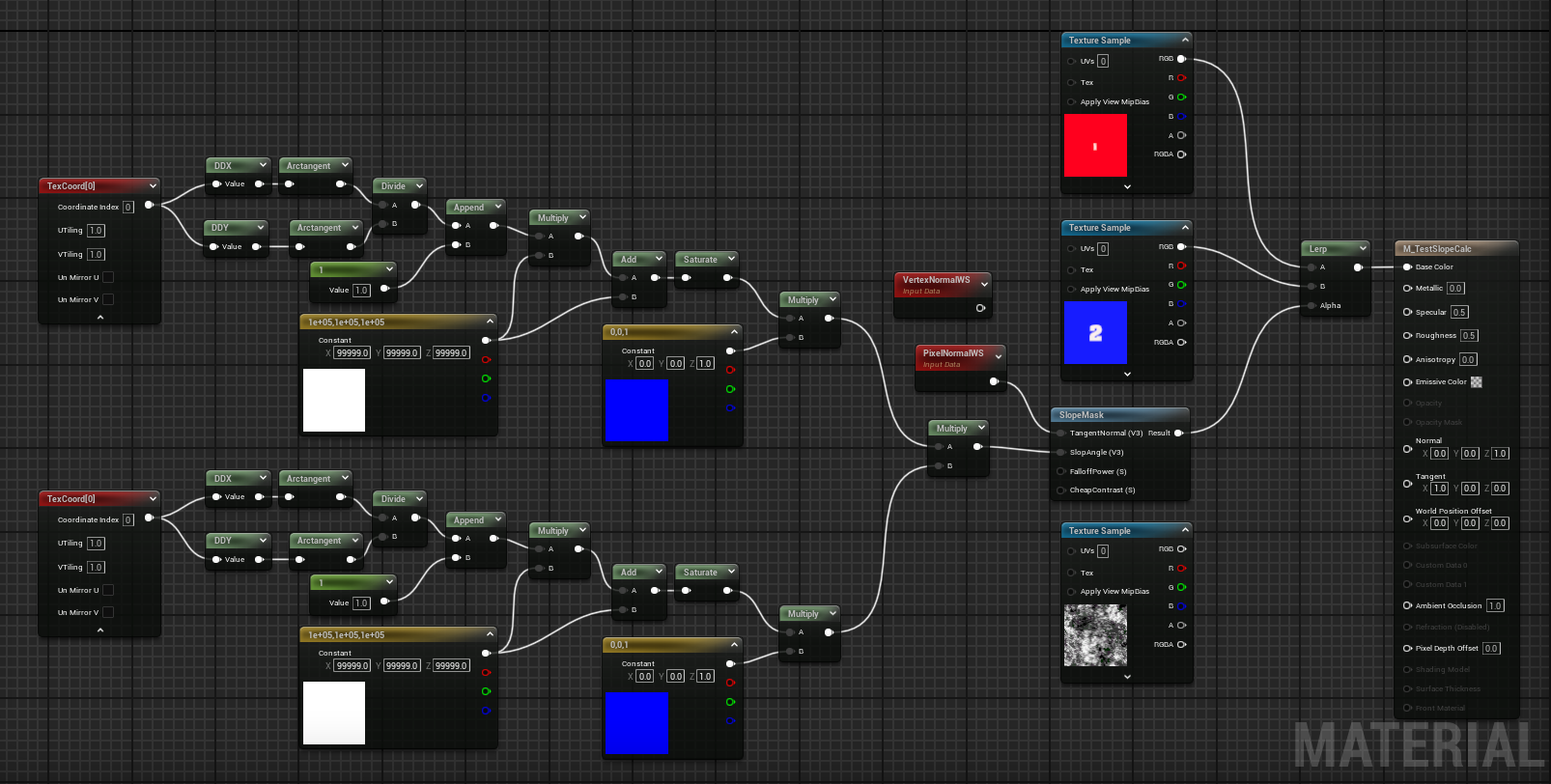
There seem to be many ways of doing this. This image shows a material which calculates the slope:
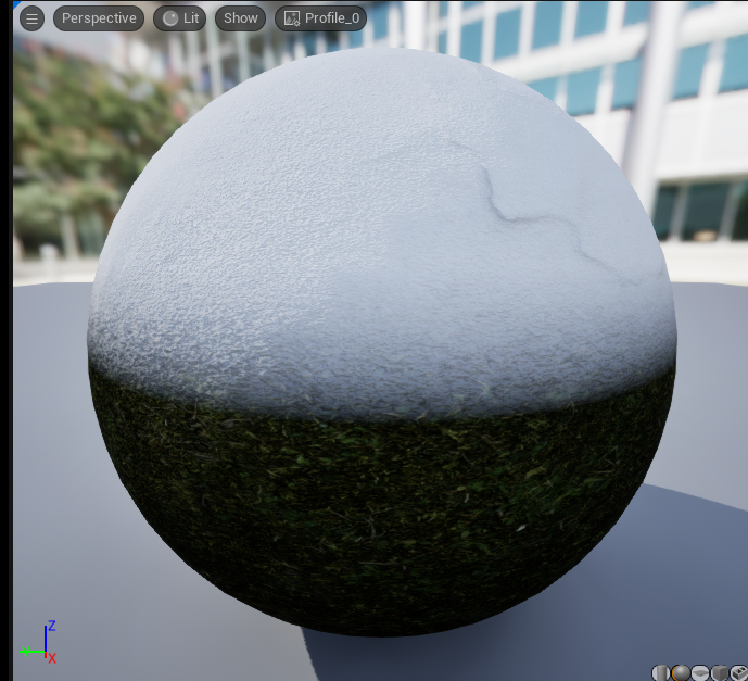
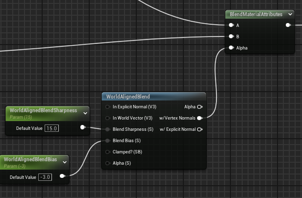
An alternative is to use the World Aligned Blend node like this:
Another alternative is to use the SlopeMask node like this:
Here is another alternative from the Project Titan example which writes materials into a runtime virtual texture and later samples those textures to do the actual display:
Distance Tiling
Distance tiling attempts to make texture tiling less obvious. It samples the base color texture (and other textures such as normals) twice, once with a small tile size for points near the player and again with a larger tile size for points distance from the player. The two samples are then blended.
This simple material has one parameter, the tiling size:
Small tiling sizes are good for near areas but bad for distant areas and vice versa. With tiling size 2 the landscape looks like this, showing tiling patterns in the distant highlighted areas:

Implementing the distance tiling technique we have two samplers (sampling the same texture) using two different tile sizes and then blend the two samples together using a lerp node:
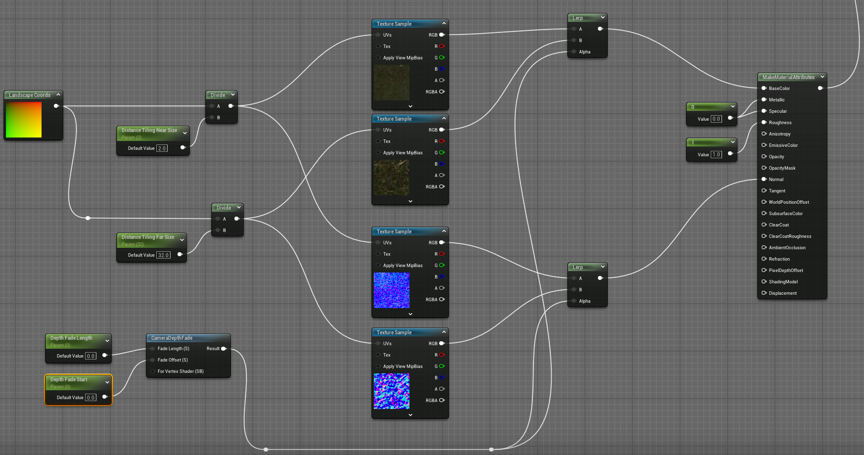
The distance sampling is controlled by two inputs to a Camera Depth Fade node. This node takes a fade offset parameter which determines where the transition between the two samples starts (relative to the camera) and a fade offset which determines over what distance the two samples a blended. Bear in mind the offset parameter is from the camera position not the third-party player position so with a short distance like 200 (i.e. 2m) the offset line might be behind the player.
If the fade offset is 0, we get a hard transition line like this:

and with a fade offset of 200 (i.e. blending the samples together over a 2m distance) we get this:
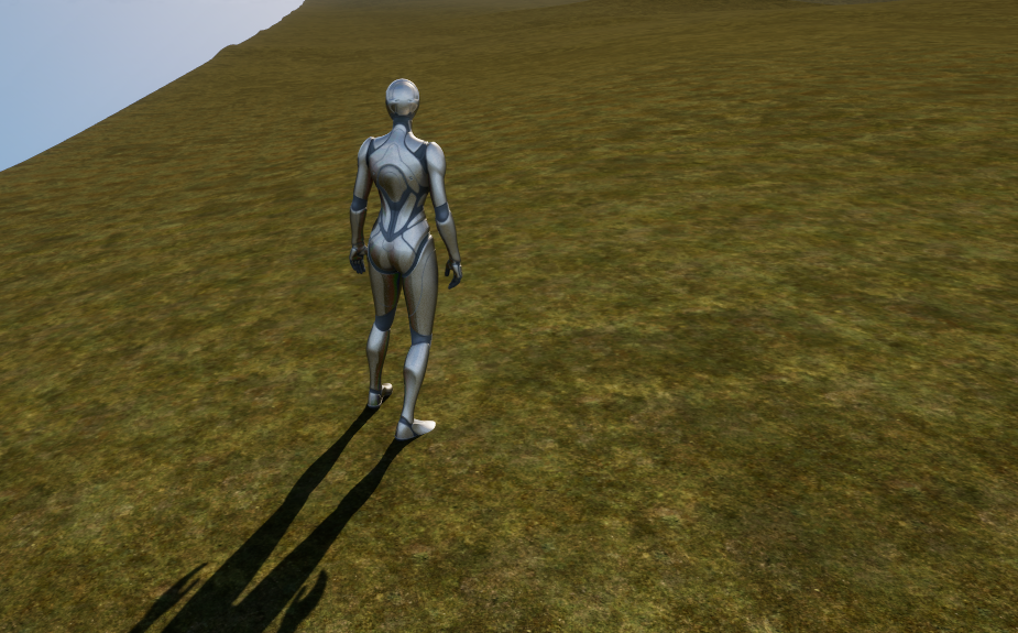
Macro Variation
When textures are tiled often the repeated tiling is visible, macro variation attempts to introduce variety to hide the tiling.
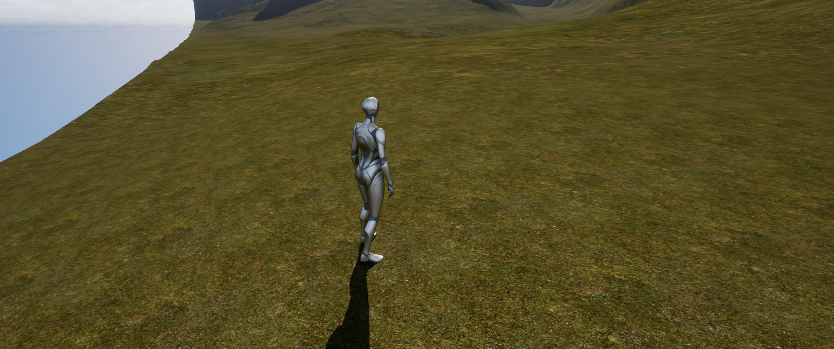
This is a very simple material:
You can see clearly the tiling pattern here:
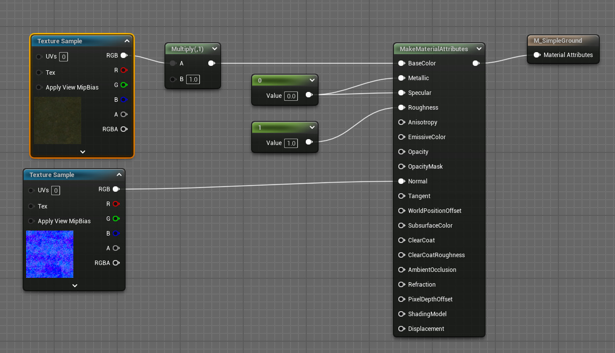
This figure shows one way of implementing macro variation. Here we sample a specific macro variation texture (called T_Default_MacroVariation) which ships as part of Unreal Engine.
The texture is sampled 3 times at 3 different coordinates, found by multiplying the incoming UV value by 3 different constant values. The 3 samples are then multiplied together:
Now the output of the macro variation calculation is included in the material like this:
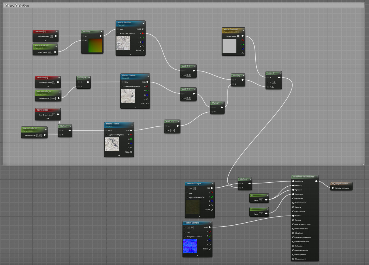
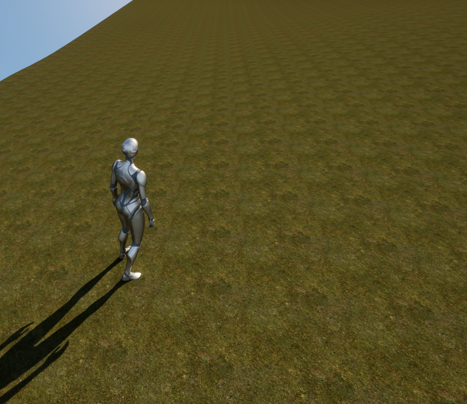
With macro variation enabled the texture tiling is no longer so obvious:
This technique can be combined with others such as distance tiling.
Texture Variation
The Texture Variation node takes incoming UV values and shifts them to break up repetitive textures. A material using it is shown here:
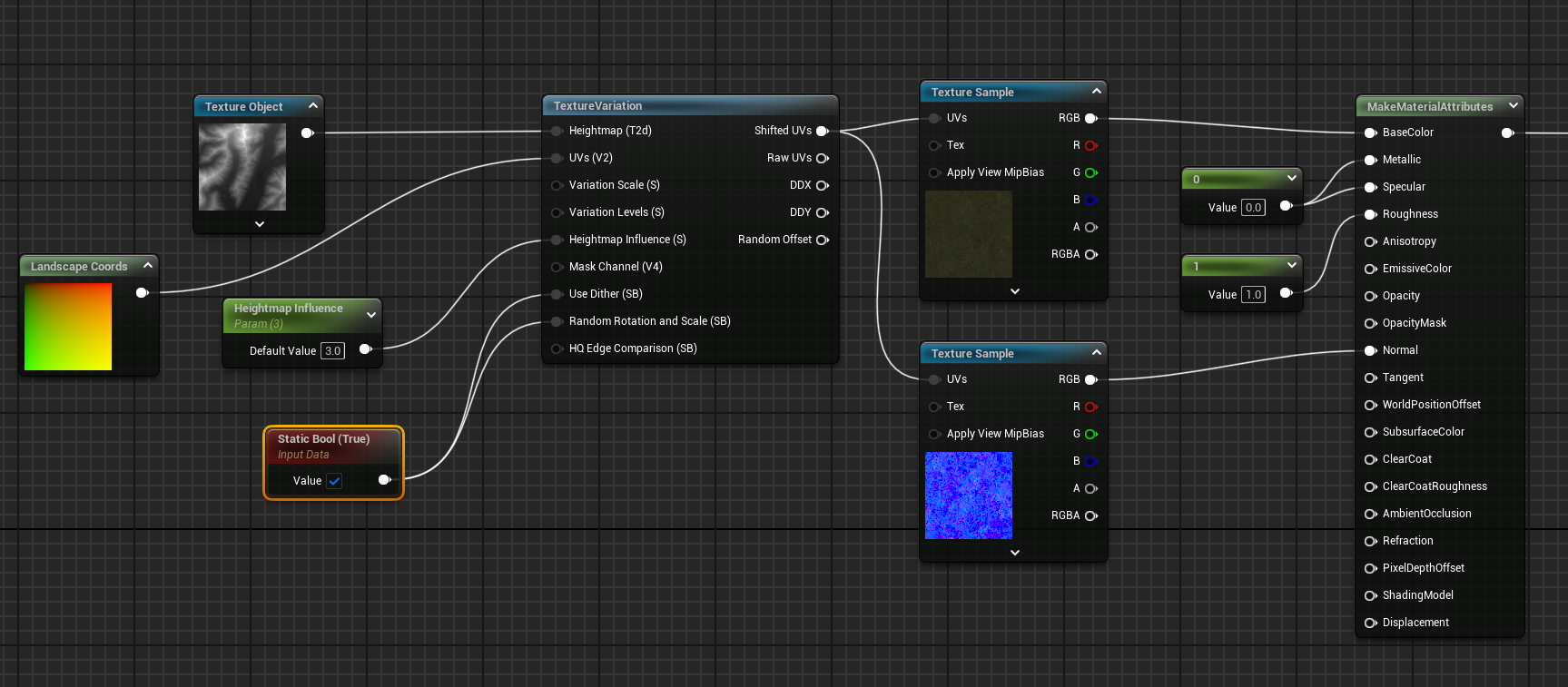
The Texture Variation node can use a heightmap - in this case it uses the heightmap from which the landscape was originally created. The shifted UVs generated by the Texture Variation node are fed into texture samplers.
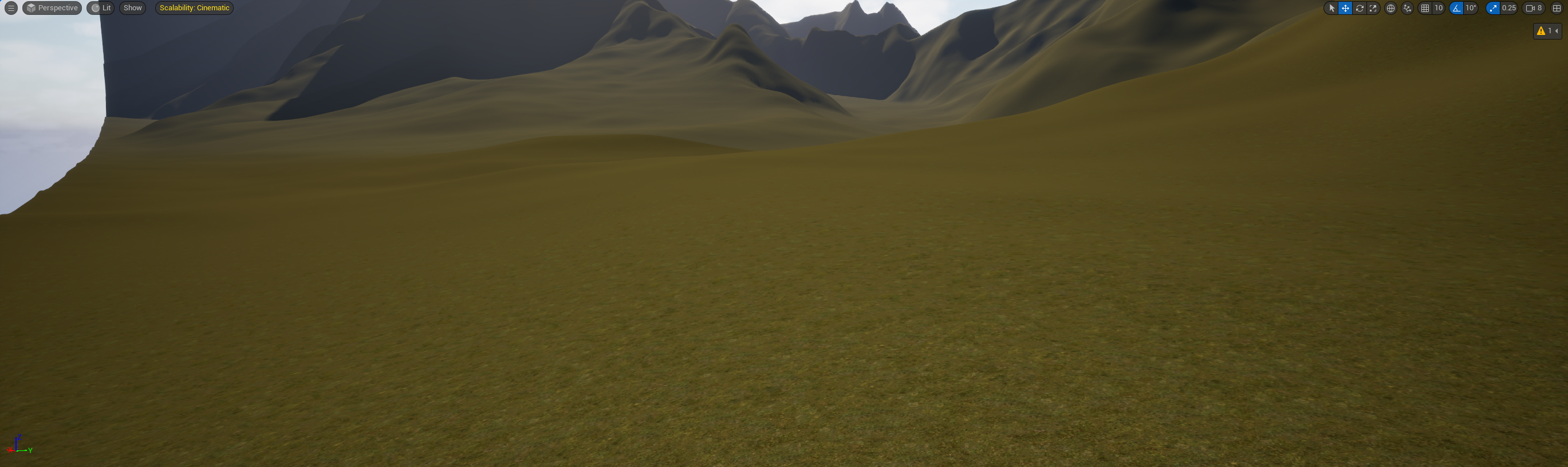
Without the Texture Variation node the landscape looks like this, with clear tiling patterns:
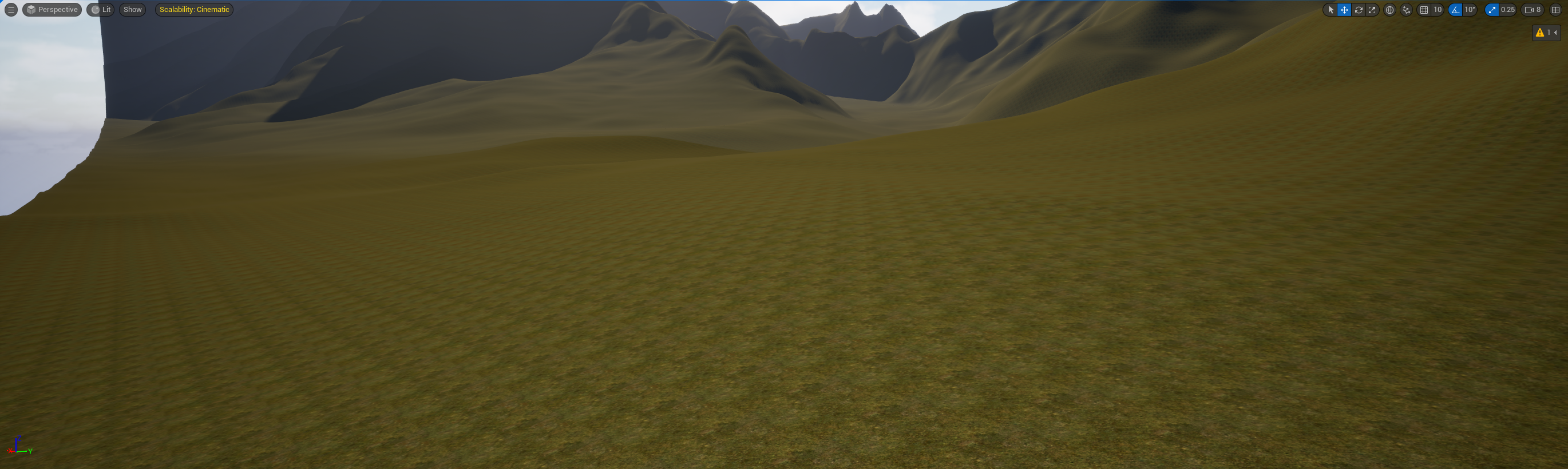
and with Texture Variation node it looks like this:
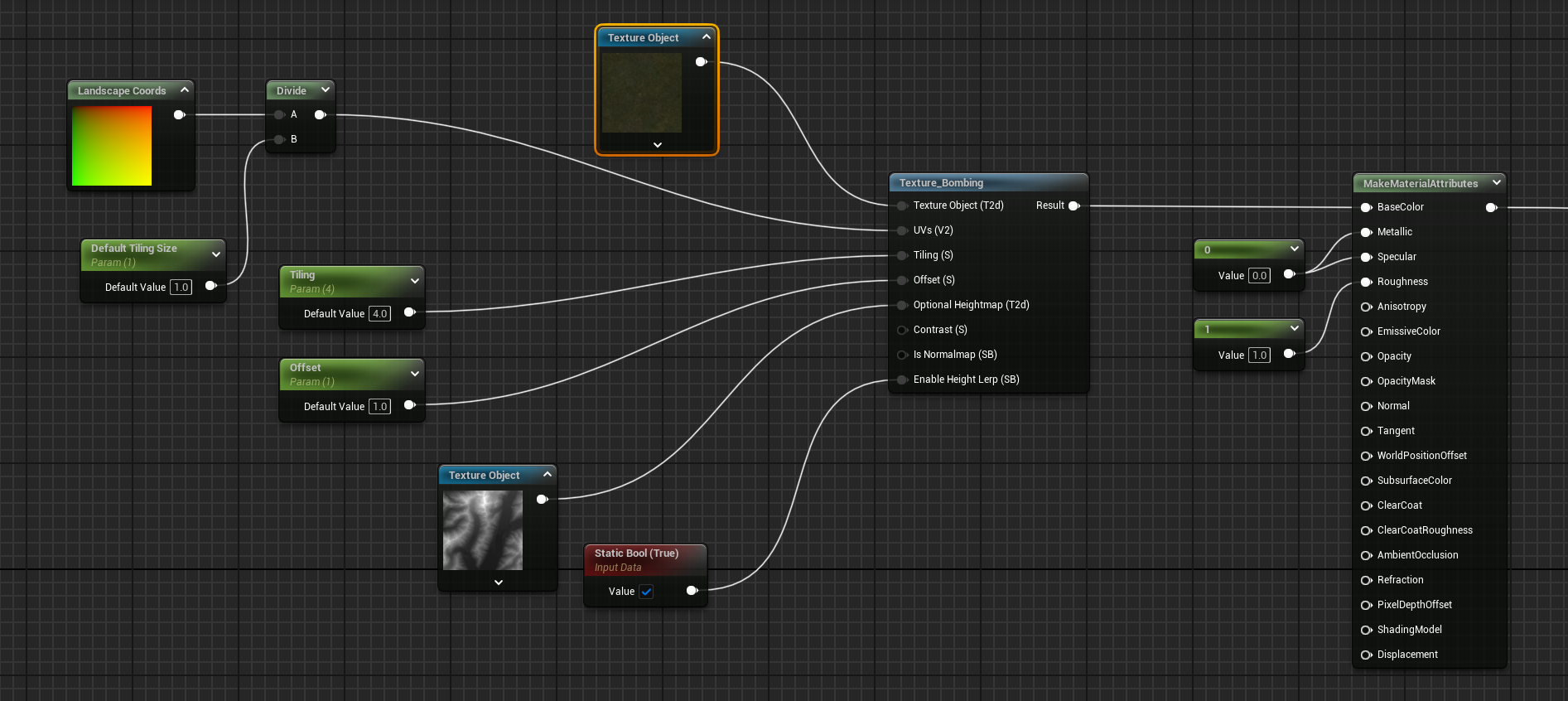
Texture Bombing
The Texture Bombing node generates pseudo-random numbers to offset the texture sample position and takes multiple samples and blends them together.
The node is used like this:
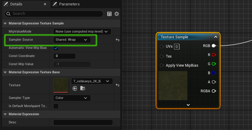
Sampler Count
A material compiles to a shader, and shaders have a limited number of samplers they can use at once. If a texture is being sampled by more than one Texture Sample node, for example when using Distance Tiling, then the Sampler Source property on each Texture Sample node should be set to "Shared: Wrap" to share one texture sampler:
Filtering
Textures have a filtering property which can be viewed by opening the texture:
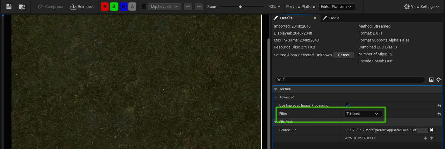
When the texture is read using a default Texture Sample node this filter property is used. However when "Shared: Wrap" is used the filter is changed to "Default(from Texture Group)" which might change the appearance of the landscape. To change using another filter it is necessary to change the the DefaultDeviceProfiles.ini file here:
[/Script/Engine.TextureLODSettings]
; NOTE THAT ANY ITEMS IN THIS SECTION WILL AFFECT ALL PLATFORMS!!!
@TextureLODGroups=Group
TextureLODGroups=(Group=TEXTUREGROUP_World,MinLODSize=1,MaxLODSize=4096,LODBias=0,MinMagFilter=point,MipFilter=point,MipGenSettings=TMGS_SimpleAverage)
+TextureLODGroups=(Group=TEXTUREGROUP_WorldNormalMap,MinLODSize=1,MaxLODSize=4096,LODBias=0,MinMagFilter=point,MipFilter=point,MipGenSettings=TMGS_SimpleAverage)
+TextureLODGroups=(Group=TEXTUREGROUP_WorldSpecular,MinLODSize=1,MaxLODSize=4096,LODBias=0,MinMagFilter=point,MipFilter=point,MipGenSettings=TMGS_SimpleAverage)
+TextureLODGroups=(Group=TEXTUREGROUP_Character,MinLODSize=1,MaxLODSize=4096,LODBias=0,MinMagFilter=point,MipFilter=point,MipGenSettings=TMGS_SimpleAverage)
....
Triplanar Projection
Triplanar projection is used to resolve problems with texture stretching. On near-vertical landscape areas such as cliff faces normal UV mapping results in triangles and textures which are stretched vertically like this:
Instead of using UVs to sample the texture Triplanar projection uses the world position. The world position has 3 components (x, y, z) but the UV has only 2 (u, v), so there are 3 possible selections, each one of which discards one of (x, y, z). Triplanar projection works by projecting each plane (x, y), (y, z), (x, z) onto the target surface and then for each pixel in the surface choosing the sample from the plane which matches the facing (from the normal) of that pixel (or more precisely choosing a weighted blend from the 3 projections).
This shot shows a cliff with Triplanar Project off, with the textures stretched vertically and cracks in the rock which should be horizontal becoming curved:
Here is the same shot with Triplanar Projection on:
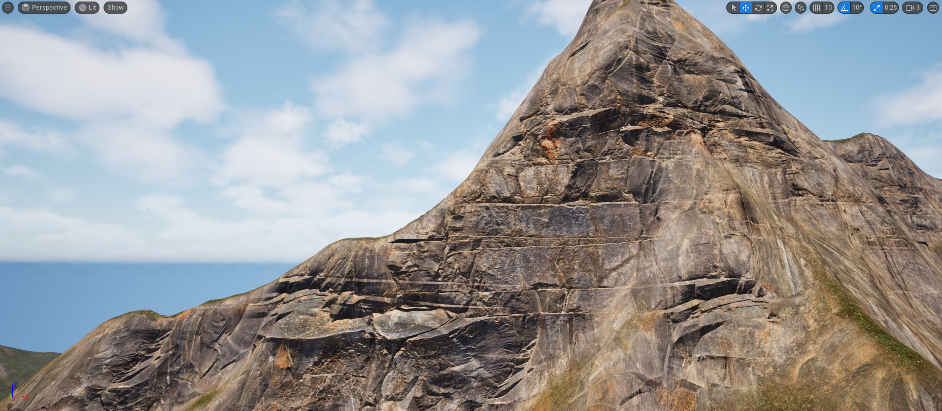
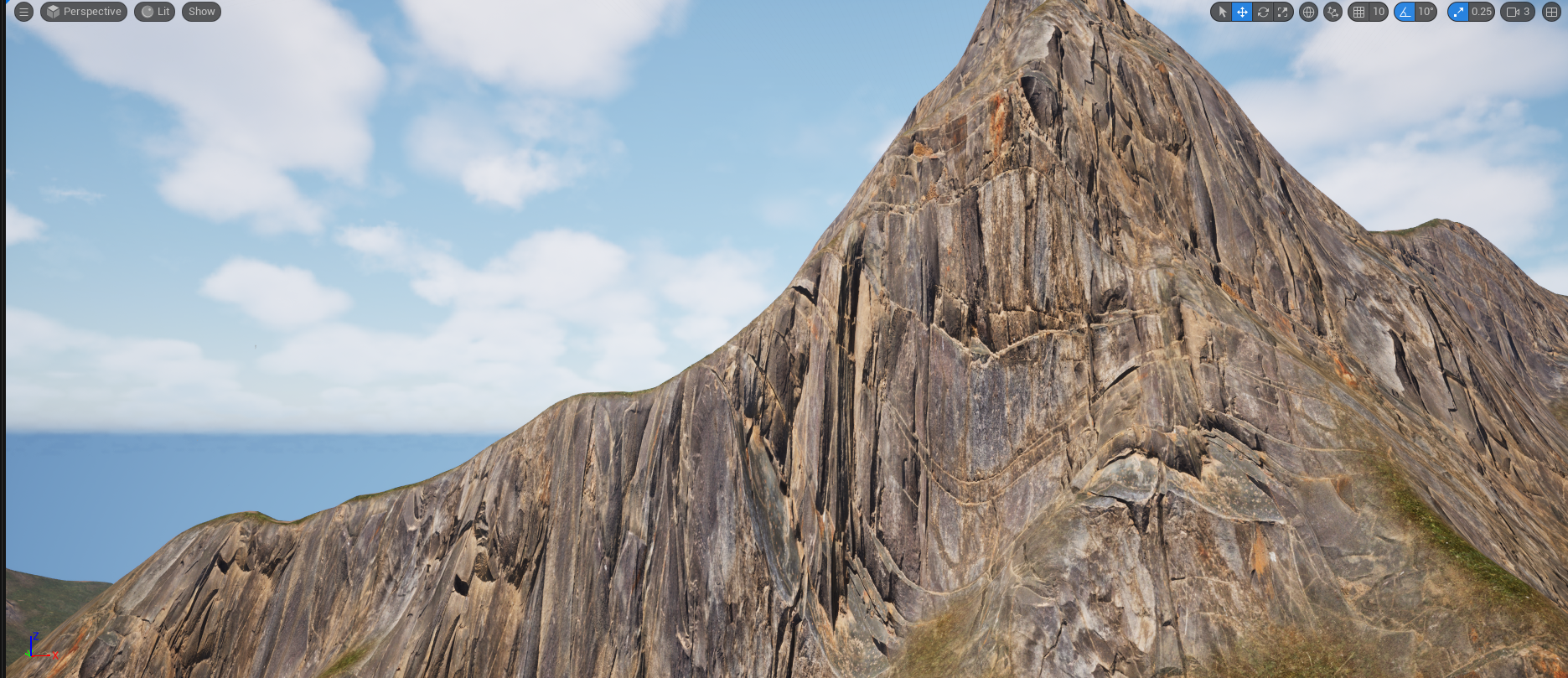
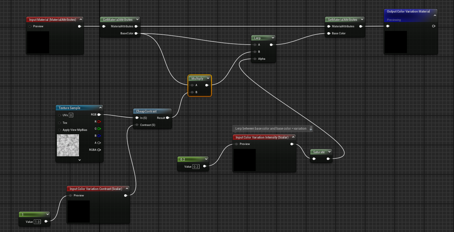
Color Variation
This can be done in many ways, one of which is to sample a noise texture, multiply the existing color by that sample, and then lerp between the existing color and the modified color like this:
Runtime Virtual Textures
Runtime virtual textures (RVT) are textures which are filled at runtime with the shading results from executing part of the landscape material.
Broadly speaking the landscape is rendered once in the first frame and the results are saved to a texture. On the first and every subsequent frame the landscape is rendered by sampling that texture, not by executing the full material.
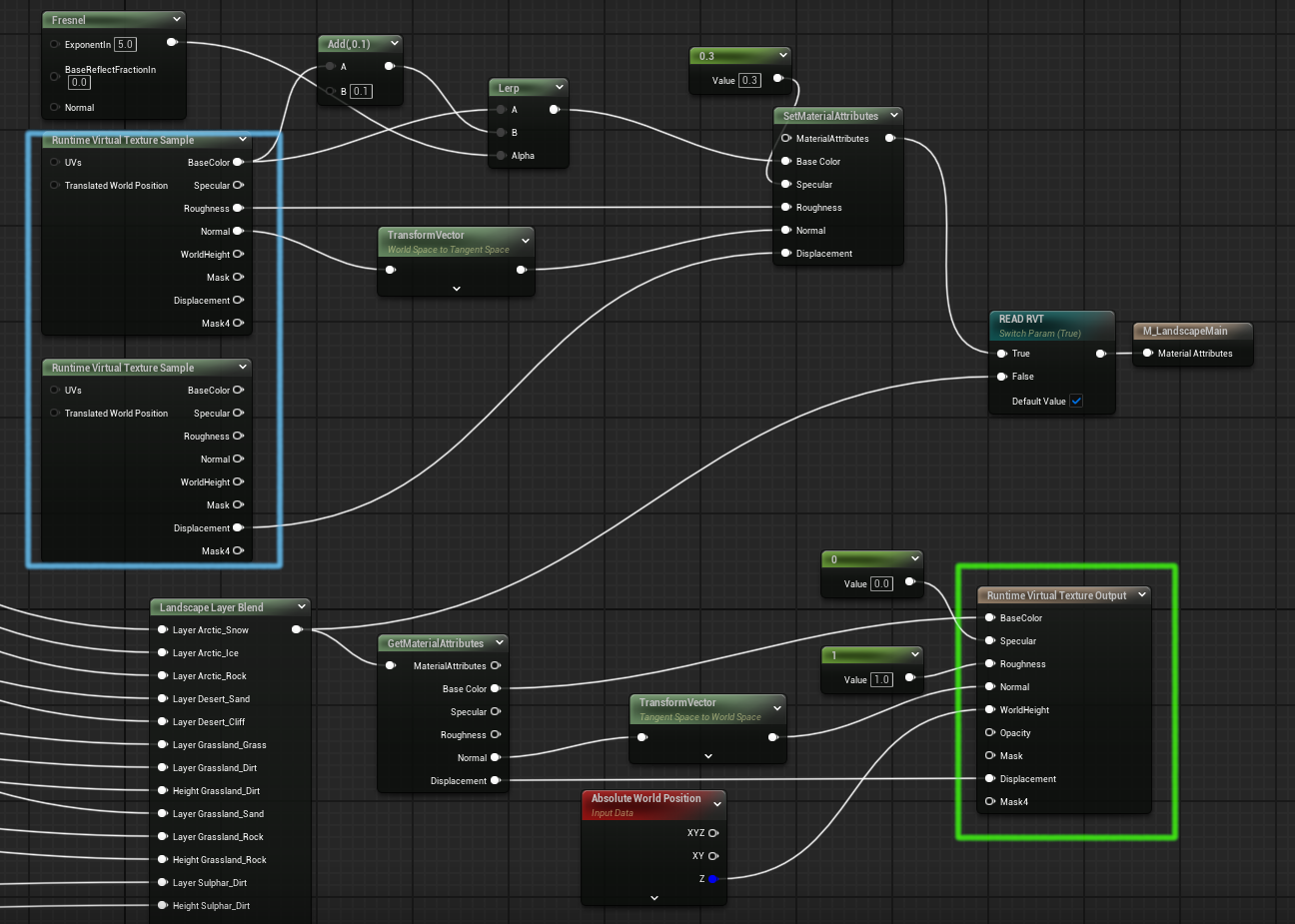
This image shows a material which has nodes to write the RVT (in green) when the shader is first run and the read the RVT (in blue) on subsequent frames:
The RVT approach gives performance benefits and enables blending of other actors such as static meshes or level instances with the landscape. Advantages and disadvantages are discussed below.
The steps involved in enabling RVT below:
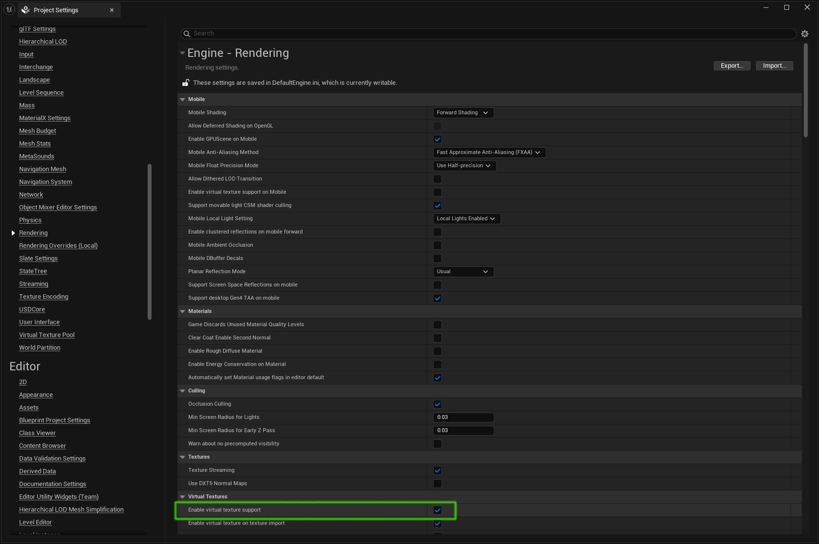
1. Project Setup
Enable this setting and restart (this recompiles all shaders so will be slow):
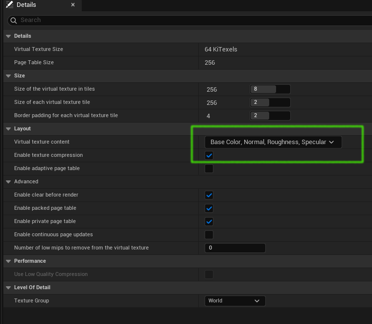
2. Create an RVT object
Right-click in the content window and chose Texture | Runtime Virtual Texture to create and name the RVT.
Open the RVT and change the Virtual Texture Context property to "Base Color, Normal, Roughness, Specular" as shown:
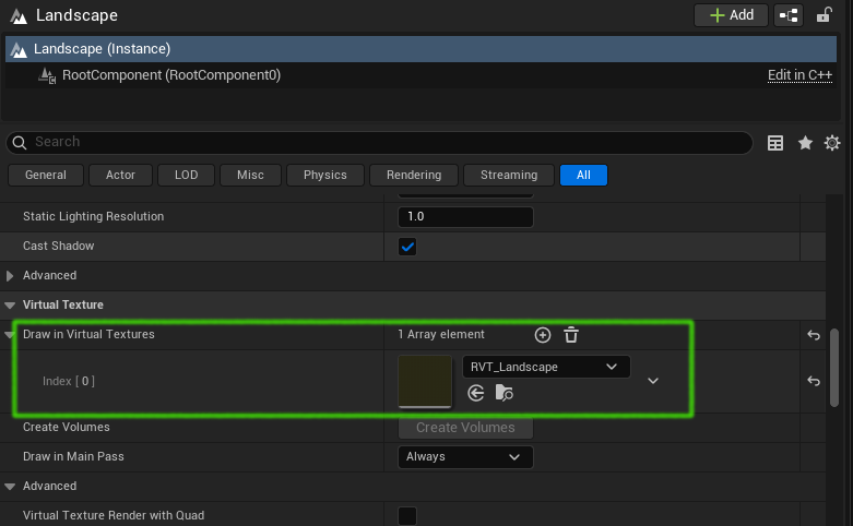
3. Configure Landscape
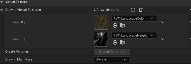
We need to tell the landscape itself that it is using the RVT, so in the landscape details panel in the Virtual Texture section add an entry to the Draw in Virtual Textures array and set it to the name of the RVT we just created:
4. Add RVT volume
In the details panel for the landscape, below where we just set the RVT, click the Create Volumes button:
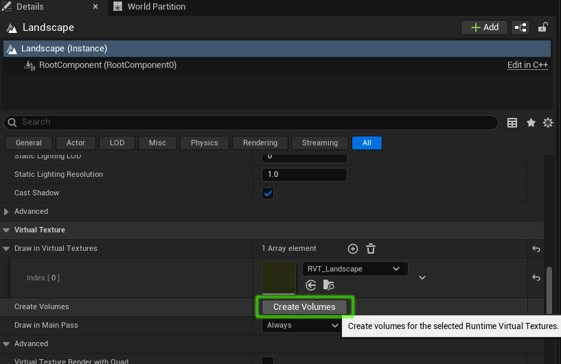
This will add a Runtime Virtual Texture Volume to the world. It will also:
- set the bounds of the Runtime Virtual Texture Volume to the bounds of the landscape
- set the Virtual Texture property of the volume to the RVT
5. Write to RVT
The landscape material needs to both write to, and read from, the virtual texture. This requires the material to have Use Material Attributes set to true.
If we have a material like this:
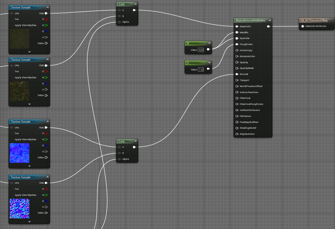
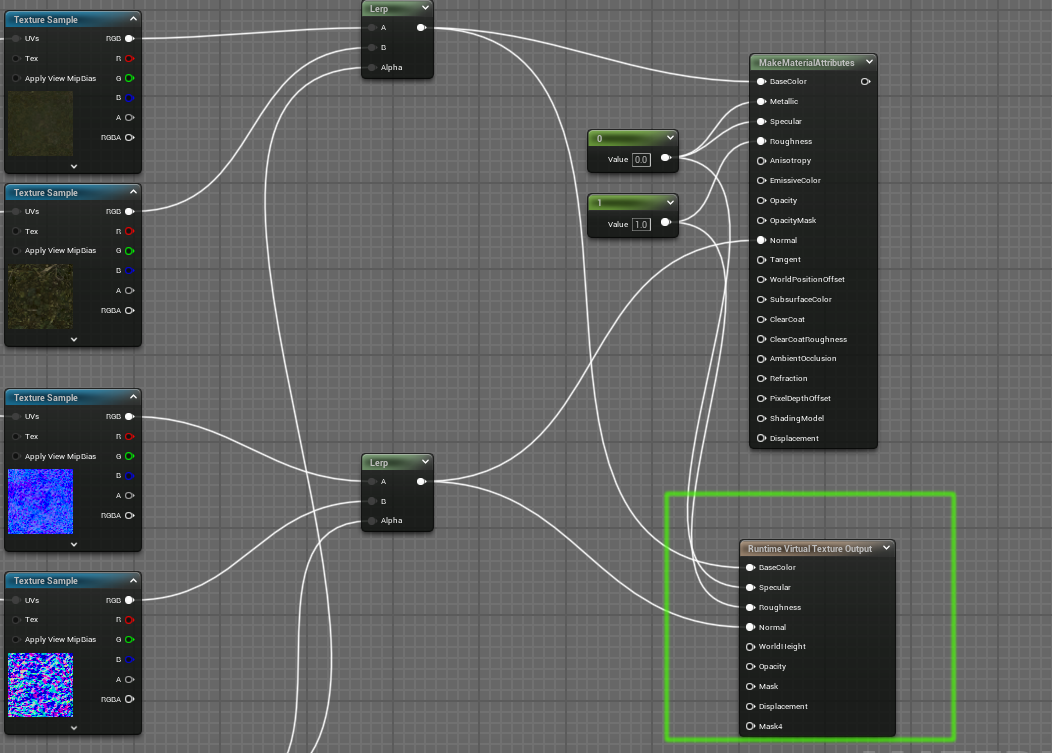
We add a Runtime Virtual Texture Output node which writes the material attributes to the RVT, and we disconnect the original output node to get this:
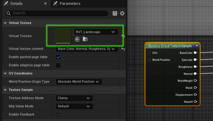
6. Read from the RVT
To read the RVT we add the nodes shown in the green box below and connect them as shown:
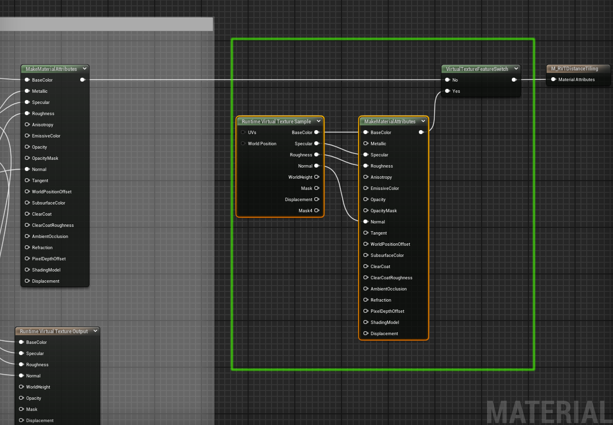
This is connected so that if the Runtime Virtual Texture feature is not available (perhaps on a phone) then the previous code path will be followed and the material will behave as a normal non-RVT material, but if RVT is available then the material attributes will be sampled from the RVT.
Select the Runtime Virtual Texture Sample node and set its Virtual Texture property to the RVT:
Multiple RVTs
It is possible to have multiple RVTs in use at the same time. The channels which can be saved in a particular RVT are limited, so if for example we want to store the both base color and the landscape height we would need two separate RVTs.
There are configured by adding them to the landscape object:
RVT Normals
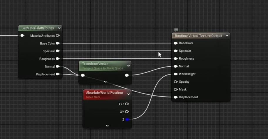
Usually, normals sampled from a texture are in tangent space. Blending of normals between the landscape and some other mesh needs to use a common space, usually world space. If you will be blending the landscape with other objects it makes sense to convert the normals to world space before writing them to the RVT. Other normals that they are blended with will also need to be converted to world space as well.
Converting normals to worlds space and back is done with the Transform Vector node.
Interactions with PCG
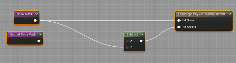
The same masks which are used to place landscape layers can be used to create Physical Materials using a Landscape Physical Output Material node and a set of Physical Material objects like this:
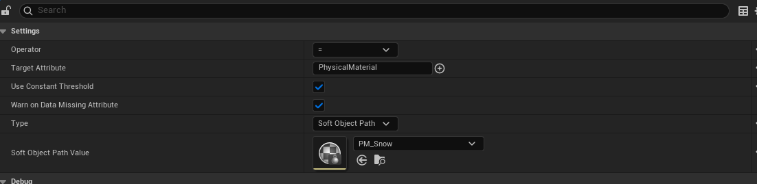
Once this has been done the names of the Physical Material objects can be used as filters in a PCG Attribute Filter node like this one, which filters for a Physical Material called "PM_Snow":
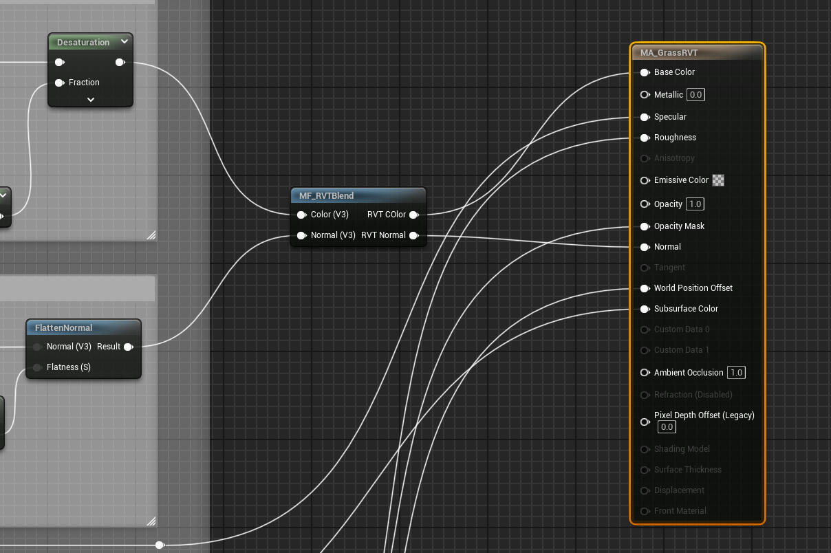
We can write a material function which samples base color and height from two RVTs, and uses the height value to blend the existing color of an asset with the color sampled from the RVT. This function is shown below. It takes a parameter specifying at what height above the landscape the blending stops:
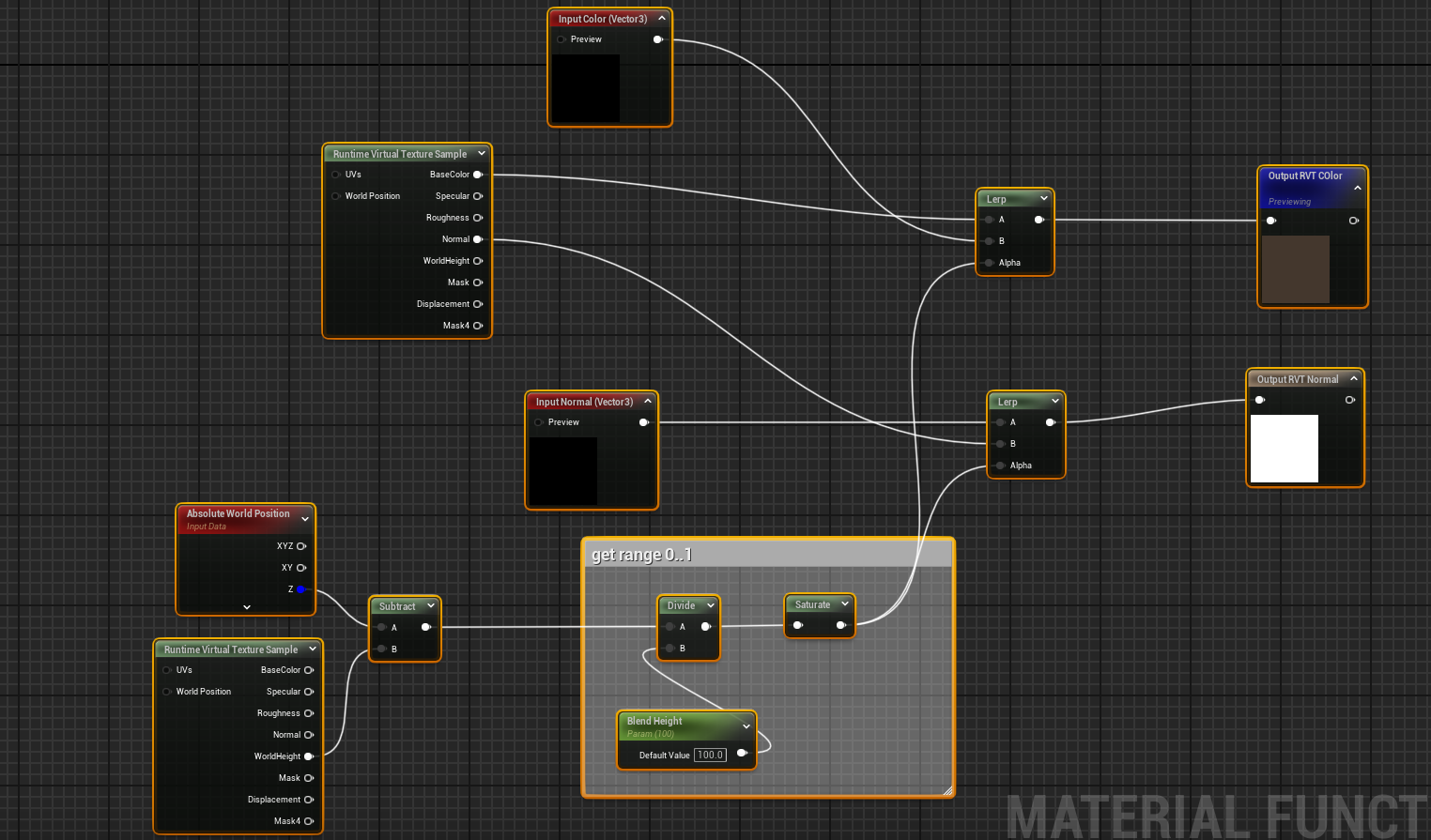
By adding this function into the material for a PCG asset such as grass, as shown below, we can make blend the color of the landscape with the color of the grass to make the grass match the landscape:
RVT Considerations
GPU Memory
Essentially using RVTs trades speed for memory. Rendering the landscape is faster but at the cost of the memory occupied by the RVT textures on the GPU.
The RVT itself is constructed of tiles, and these tiles are stored in GPU memory if they are being sampled. Tiles which are not being sampled, because they are maybe behind the player or behind landscape features such as mountains are not held in GPU memory.
If the player is close up to a terrain feature such as a cliff, or looking out to sea, few texture tiles are required and the pool usage is low. Also if the player is far away from the terrain may tiles are needed but use of LOD means those tiles are smaller because they are only sampled at low resolution for distance terrain.
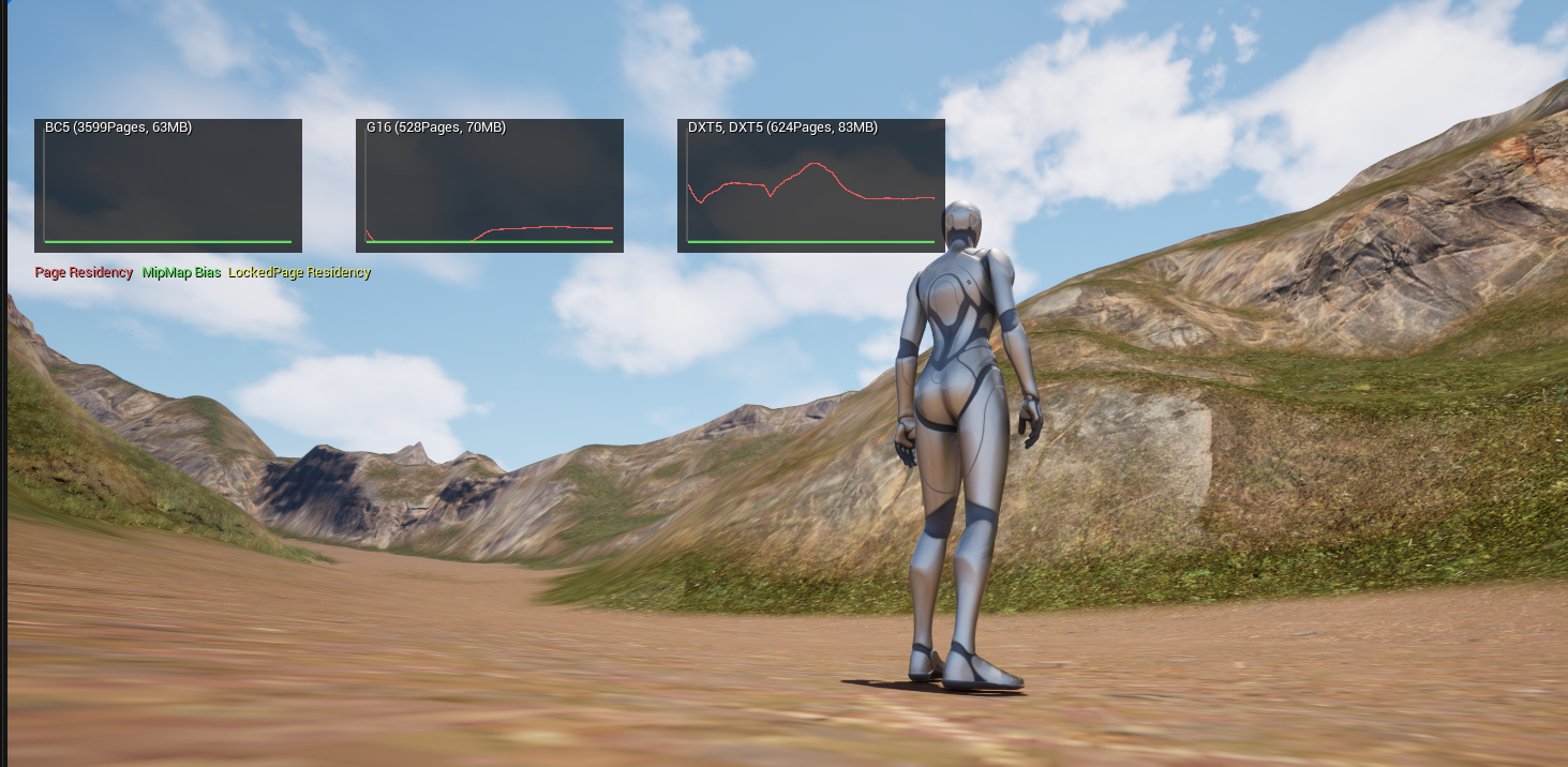
The RVT textures are held in the RVT texture pool. This can be visualized using the console command:
r.VT.Residency.Show 1
This shows how much of the pool is being used for RVT textures:
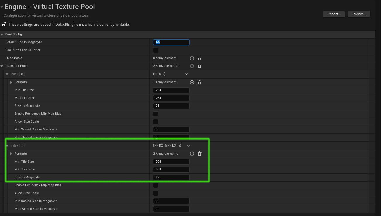
To specify a fixed maximum pool size, change the Virtual Texture Pool the project setting like this:
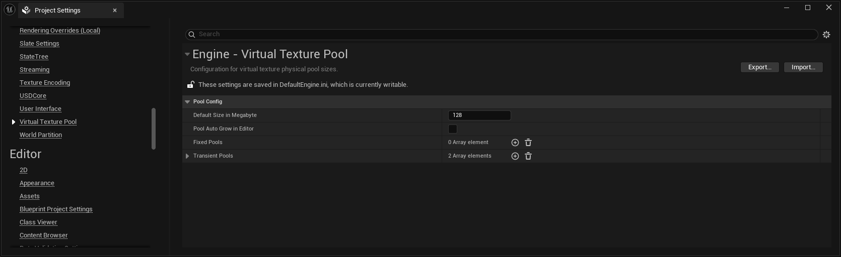
In Unreal 5.5.1 changing the Default Size in Megabyte might have no effect
if (by default) a specific transient pool is already configured for that
texture type, like the one shown here:
If there is not enough memory in the pool then the textures will appear blurry.
No Camera Support
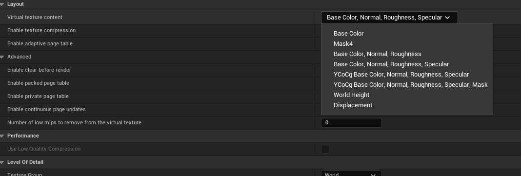
Only some channels can be saved to the RVT, as shown here in the RVT properties:
A material might have camera position dependent nodes, for example when using the Camera Depth Fade node used in Distance Tiling described above. Because RVT writes into the texture from above the landscape it has no concept of variable camera distance, so Distance Tiling will not work.
References
-
Landscape Optimization Using Runtime Virtual Textures - Building Worlds In Unreal
-
How To Make Landscape Layer Materials with Natural Height Blending in Unreal Engine 5
-
Create a Photorealistic Mountain Landscape in Unreal Engine 5
-
Triplanar, Dithered Triplanar, and Biplanar Mapping in Unreal
-
View, World, Object, & Tangent Space - Shader Graph Basics - Episode 10